486 B
486 B
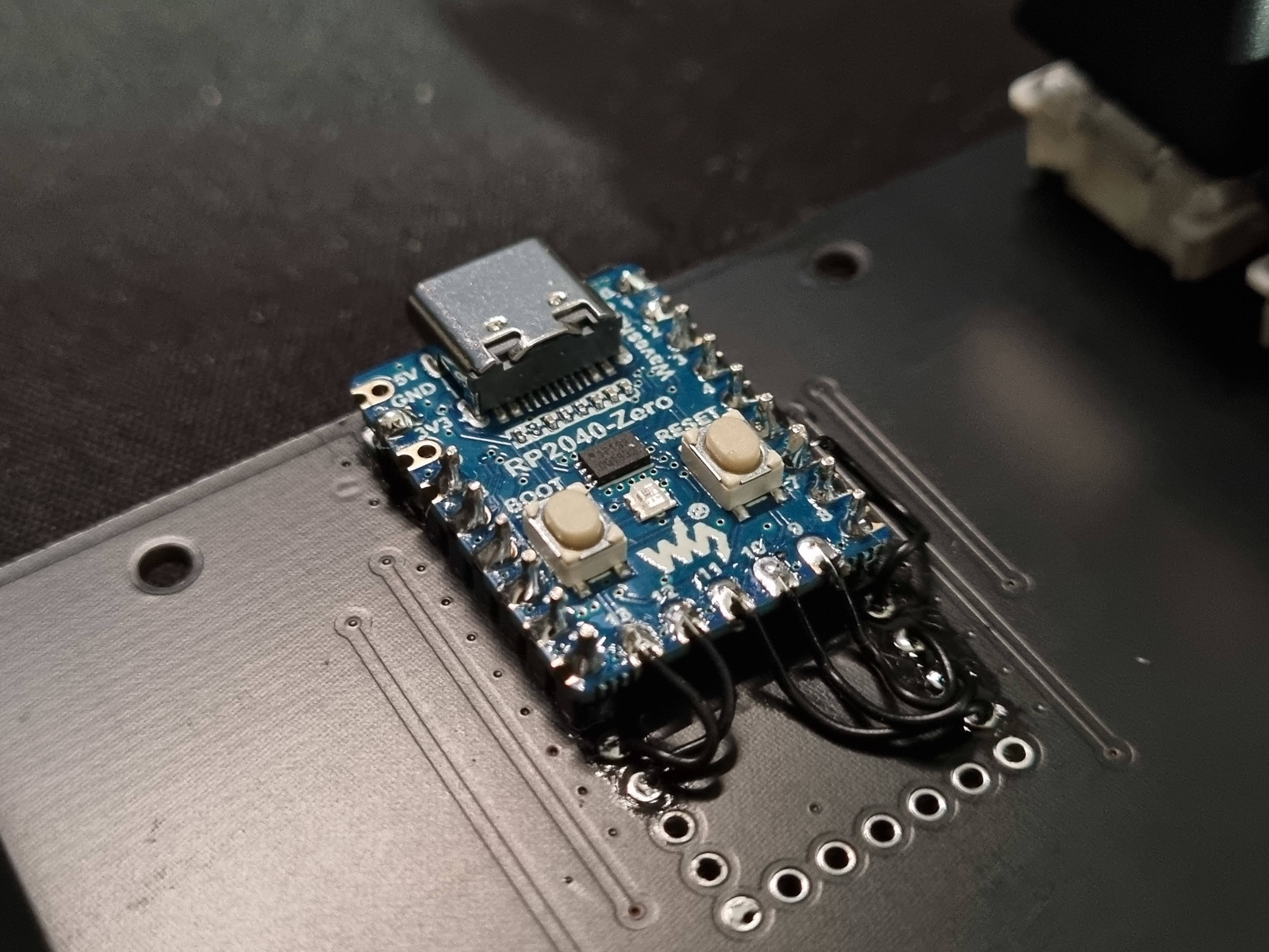
Patch instruction to solder rp2040-zero module instead of teensyLC module
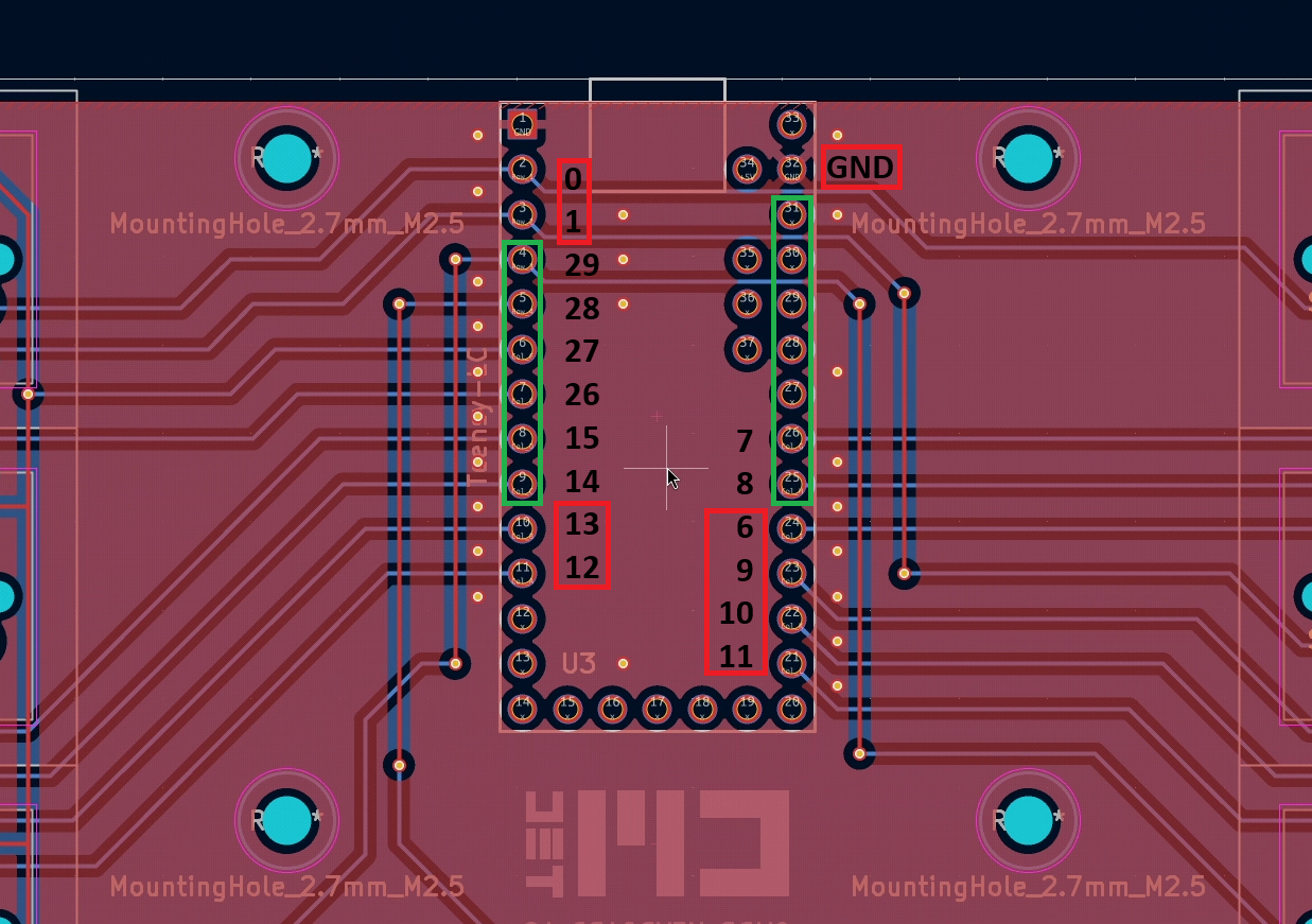
- Solder one x6 and one x7 pin headers on the green marking.
- Prepare wire and solder on GND pad on the PCB.
- Prepare wires and solder on gpio 0 and 1 on the PCB.
- Solder rp2040-zero on the two pin headers.
- Solder GND, gpio 0 and gpio 1 on the rp2040-zero.
- Solder wires according to picture above between rp2040-zero and PCB.